
Introduction to Electronics
Electronics is a science of controlled movement of free electrons in a matter. The first electronic component was “triode” developed in 1906. Electronics is used in household, factories medical science and defense sector.
All electronic components can be divided into two categories:
- Active devices; and
- Passive devices.
Active devices are such type of electronic components which are first given supply of electricity to carry it to working condition and then energy is generated by these components. E.g., – IC or Integrated Circuit.
Passive devices are such electronic components that do not produce energy. They function as supporting devices. E.g. – Capacitor, resistor.
What is Electronics?
Flow of electric charge from one terminal to another terminal is defined in electronics. This flowing electrical charge is called current electricity.
Flow of electrical charge is not visible to the eyes but can be felt or seen in the form of light, energy or magnetic form. Flow of electric charge in any metallic wire means flow of electrons.
Now the question arises that how and why electrons flow in any wire. It is important to understand electron to find out the answer.
What is electron?
The smallest particle of a matter which contains all the properties of that matter is called “molecule” which is found in free state in nature. These molecules have been further divided into atoms. Atoms do not have properties of that matter. Atoms consist of nucleus and few electrons which rotate around the nucleus at a very high speed. Nucleus consists of protons and neutrons. Electrons are negatively charged, protons are positively charged are neutrons are electrically neutral. Some of the electrons can be easily dissociated from the atom which is called “free electron”. This dissociation of electrons causes flow of current electricity in a metallic wire.

Atom Structure
Types of Matter?
Flow of electric current from any matter depends upon the number of electrons on its outermost orbit (valence shall), which means that the rate of current flow in different matter will also vary because the number of electrons in different matters vary. A matter can be divided into three categories on the basis of electricity flow and number of free electrons. These categories are:
- Conductor: The matters which have free electrons on its outermost orbit are called “conductor” because free electrons easily move from one atom to another atom. Generally all metals are good conductor of electricity. E.g. gold, silver, copper, aluminum.Copper is a Good Conductor of Electricity
- Insulator: The matters through which electric current cannot flow are called bad conductors or insulators. Outer most orbit of these atoms are fully saturated. So, there are no free electrons. E.g. rubber, plastic, mica, glass. Some insulators can store electric charge. These matters are called di-electric.Plastic is a Bad Conductor of Electricity or Insulator
- Semiconductor: semiconductor matters are more resistant to the flow of electric current that conductors, but less resistant than insulators. The number of free electrons is very low. As a result there is a feeble flow of electricity through these matters. But when these matters are mixed with other matter with some special characteristics in small quantity, number of free electrons increases considerably. As a result, there conductivity increases. E.g. – Germanium and Silicon.Silicon is a Good Semiconductor


Flow of Electric Current in Conductor Wire
In normal condition, free electrons of a conductor wire remain in their orbit due to gravitational force of nucleus. When electrical pressure is applied on the terminal of a wire through battery, the electrons from the outermost orbits are dislodged from the orbit and are attracted towards the positive terminal of the battery because electrons contain negative charge. New electrons are continuously replaced through the negative terminal of the battery and the flow of electrons through the wire continues. This is called electric current flow.
When the electrons move from its position, the space is vacated. This vacant space is called “HOLE” which is positively charged. The following electron is attracted to this positively charged “HOLE” and leaves a new “HOLE” on its position. This is how the flow of current is directed from negative terminal to positive terminal of the battery. The electrons from negative terminal of the battery are emitted due to force of attraction of the positively charged “HOLE” and fill up the HOLE. This process continues.
Types of Electric Current
There are two types of electric current:
- Direct Current (DC): This is a type of current flow where direction of flow is always constant. The electric current generated from cell and battery is direct current (DC). The direction of flow being constant, its frequency is zero. One terminal of the DC is positive (+) and the other terminal is negative (-).DC Current Symbol
- Alternating Current (AC): The flow of electric current which change its direction and rating with time is called alternating current. The rating of current in one direction increases from zero to maximum and again drops to zero. Again from other direction the rating increases from zero to maximum and re-drops at zero. Due to variation on both the directions the flow of current looks like a wave in graphic view which is called sine wave. In alternating current there are 50 cycles (waves) per second. One terminal of the AC is phase and the other is neutral.AC Current Symbol
The Main Phenomena of Electricity
Three phenomena are affected during flow of electric current through any conductor wire:
- Electric Pressure: The force applied for moving the electrons through conductor wire is called electric force or electromotive force (EMF). Electromotive force is from high to low.If two charged spheres, one of which carries more charge than the other, are connected with a conductor wire, a flow of current will start and this flow will be directed from higher charge to lower charge. The difference of EMF between two spheres is called “potential difference”. Potential difference is measured in the units of “Volt”. A volt meter is used for measuring potential difference which is connected parallel to the lead.Volt Meter
- Electric Current: The flow of free electrons through a conductor wire due to electric pressure is called electric current. As water from a tank flows out due to pressure of water at the base and the force at the bottom and flow of water are two different things, similarly, electric pressure (EMF) and flow of electricity are different things. Current is measured in the unit of “ampere”. An ampere meter is used for measuring electric current which is connected is series of the load.Ampere Meter
- Electric Resistance: The obstruction on the way of electric current flow is called electric resistance. Every conductor has resistance capacity, which is called the Resistance of the Matter. The unit of measuring the resistance is called Ohm. The symbol of Ohm is W.Ohm Meter


Ohm’s Law
Ohm’s law is the basis of principal of electricity and electronics. This law co-relates current, voltage and resistance in any electrical or electronic circuit. According to Ohm’s law, current is directly proportional to voltage and inversely proportional to resistance. If resistance in any circuit is kept constant and voltage is increased, the rating of ampere will be higher in this case. Similarly, if voltage is kept constant and resistance is increased, in this case the rating of current will degrade.
Ohm’s Law Formula
- V = IR, V = Electric Pressure (Volt).
- I = V / R = Electric Current (Ampere).
- R = V / I, R = Electrical Resistance (Ohm).
Examples:
- Measurement of current when voltage and resistance are given:
V = 6 and R = 3; then
I = V/R = 6 / 3 = 2 Ampere. - Measurement of volt when current and resistance are given:I = 2 Amp and R 5 W; then
V = IR = 2 * 5 = 10 Volt - Measurement of resistance when voltage and current are given:
I = 2 Amp and V = 10 V; then
R = V / I = 10 / 2 = 5 Ohm
Electric Circuit
The path of a current flow where electricity is consumed is called electric circuit. Conductor wire is required for inter connecting voltage source, lead, fuse, ON / OFF switch etc to a circuit.
Types of Electric Circuit
There are 5 types of electric circuit:
- Close circuit: When load performs its function, the circuit is called closed circuit. In this case the rate of current flowing in the circuit depends upon the load.Closed Circuit
- Open Circuit: When a circuit is switched OFF or any wire or component of the circuit is broken, the circuit is called open circuit. There is no flow of current in the circuit in this situation.Open Circuit
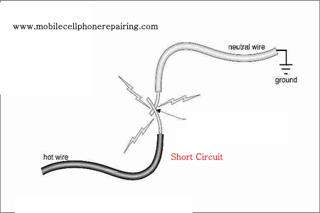
- Short Circuit: When terminals of voltage source are interconnected, it is called short circuit. Maximum current flows in the circuit in this situation. Circuit gets short due to mutual contact of two conductor wires or if the lead is short.Short Circuit
- Series Circuit: When two or more loads are connected serially, it is called series connection. The total voltage capacity of the power of load should be equal to the input supply.Series Circuit
- Parallel Circuit: When two or more loads are interconnected at each terminal and finally connected with input supply, the circuit is called parallel circuit. Voltage capacity of all the loads should be equal to the input supply. Load capacities of each load may vary.Parallel Circuit


Earthing
Three-pin plug is used in the main lead of equipment like computer, laptop, mobile phone charger, geyser monitor, cooler, ac etc. Out of these three pins, two pins are used for phase and neutral and the third central pin is used for earthing. Earthing pin is connected with the body of the equipment. There is a possibility of current leakage in the equipment consuming high electricity. The current flowing in the body of the equipment is grounded through earthing pin.
Power
The sum of the multiplication of voltage and current is called power. It is measured in unit of Watt (W)
No comments:
Post a Comment